


Deck Load Capacity And Tributary Area: How they relate
What a great question.
The question around deck load capacity is one I receive often from visitors asking how much weight should they design their deck for.
The
discussion quickly leads to the overall strength of the framed
structure. But that is only one part of it.
That is because any
analysis of what load a structure may bear upon itself and its foundation must involve the support post network and soil bearing
capacity.
The Entire Deck, Footings And Soil Are A System
It truly is a system - not unlike a chain - where the weakest link will lead to the failure of the deck.
People Get Intimidated By The Thought of Math and Engineering
Many people are intimidated with trying to figure out the load capacity for a deck.
Even
some contractors are not sure where to begin so they just over build –
which may be entirely unnecessary and cost you more money. Another
problem that can arise from over building is a sinking deck.
Yes,
even if you build a strong deck it can gradually sink into the soil if
you do not consider the size of footings with respect of the load
for the deck. Once your deck starts sinking it can rip the ledger board
away from the house or you will have to jack up the sunken area,
excavate and pour a new larger footing.
That is what we will cover in the second half of this article.
But Some Basic Math Is All That Is Needed
The good news is the concepts and the math used for determining loads on decks and other structures are quite simple.
I will explain how to do it and then you can go build that deck with confidence knowing it will be strong and stable and standing years from now.
Let's Start At The Top And Work Down
The
first area to think of is the actual framed deck. This structure is
comprised of perimeter joists - sometimes called rim joists or band
joists. Then there are the joists in the middle. These are sometimes
called infield joists or inner joists. You will hear a number of terms.
This framework is supported by a number of beams - sometimes called
carrier beams because they "carry" the load of the structure.
Design Load, Dead Load, LIve Load - What does this mean?
Design Load
The IRC and other similar codes in other countries, like Canada or the UK all work from a similar starting point for what a floor deck should be engineered to support.
These standards are borrowed
by deck builders and come from the actual code requirements used for
the floor deck of a residential home.
The load that is placed on
your deck is expressed in pounds per square foot (psf) and the total
load or more appropriately, the design load, is comprised of the dead
load and the live load.
Dead load is basically the load created
by the weight of the deck itself. This is usually about 10 psf.
Live
load is created by all the extras like furniture, planters, and people.
This is usually about 40 psf. Together the design load would be 50 psf.
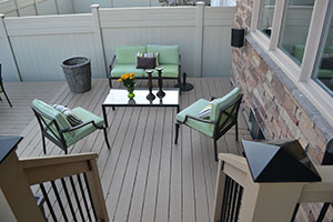
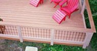
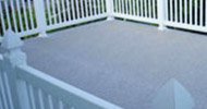
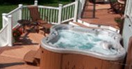
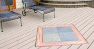
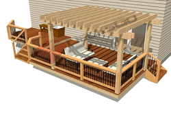
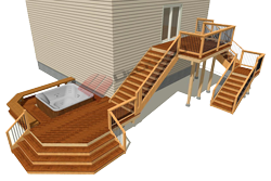
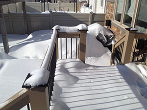
Snow load anyone?
Of course, if you expect a lot of snow to sit on your deck over the winter or envision an 8,000 lb hot tub on the deck this could increase the required load capacity of your deck up to 100 psf.
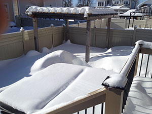
Not all locations experience seasonal changes like the one depicted in the series of photos. But given the amount of snow piled up on this deck you can see why it is important to consider all the forces that will be at work on your deck and then calculate and build accordingly.
Framing For The Design Load
To avoid referring to complicated engineering tables and for the purpose of building a deck, let us start with the idea that using standard 2x8 softwood lumber at 16" o.c. joist spacing your deck will easily meet the 50 psf threshold.
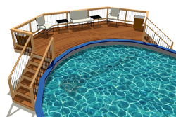
What About Snow Load Or a Spa Tub
Yes, this is a concern but the
net effect or changes you might have to do to increase the strength of
the deck could be as simple as using 2x10 joists at 12" o.c. spacing.
The framed structure will typically handle the added weight quite easily.
The worry will be your beam spacing, support post size and most importantly how many footings and how much weight will they impose directly on the soil below.
This is critical because if you overload the soil more than it can bear, the deck will start to sink. A very bad thing.
now Let's find the tributary areas of a deck
To determine the maximum load capacity of your deck, start by calculating its total area and multiply by 50
psf. So, a 100 sqft deck would be designed to support 5000 lbs.
Do not get confused with what weight you might think or want to load the deck with.
If
you drove a dump truck over it, yes this would throw all our
calculations out the window. But we are building a deck to support
known loads consistent with the purpose for which the structure is known
to be used for and the 50 psf number has a safety factor in it. That
is why engineers have settled on this as a safe value.
So with a
total deck load capacity of 5000 lbs we now move to the "slightly" more complicated
discussion about tributary areas and how this overall load is now
distributed around the entire deck and onto the soil below. Stick
around. This is the fun part.
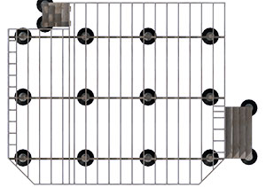
Our example: a 10' x 10' Deck
Four Tributary Zones: A, B, C, D
Our
deck is as simple as it gets to illustrate the concepts deck
load capacity and transfer of weight within each tributary area. This
deck is 10`x10` or 100 sqft.
There is a ledger board attached to
the house. The joists run perpendicularly out from the house for 10 feet
at 16 inches on center. The carrier beam runs perpendicular to the
joists with its center at 8 feet from the house and the cantilever
beyond its center point is 2 feet.
There are three support posts
3.5 feet from center to center. The beam cantilevers 1-6` past the
outer posts to the perimeter of the outer most joist.
For example the unsupported section from the ledger board to the beam is a distance of 8’. Therefore the first midpoint is 4’ from the house and marks the separation between supported load areas as you move outwards from the house. Area A equals 4x10 or 40 sqft.
Defining Tributary Areas Of The Deck
There are four tributary areas on this deck: A, B, C and D.
Tributary
Area A is confined between the midpoints of its two adjacent support
members, the ledger board, and the beam. The outside perimeter joists
confine the width of the area.
Area A
For example the unsupported section from the ledger board to the beam is a distance of 8’.
Therefore the first midpoint is 4’ from the house and marks the separation between supported load areas as you move outwards from the house.
Area A equals 4x10 or 40 sqft.
This means that the force exerted over the deck between the beam and the
house is supported 50% by the ledger board and house and 50% by the
beam.
Area B
Area B extends from the 4’ point outward to the beam and beyond to the end of the deck.
Since there is no support member past the
beam the length of this load area is 6’ (from the 4’ mark to the 10’
mark).
The width of Area B extends to the midpoint between the end post and the center post.
The
end post is 1.5’ from the end of the beam. The distance between the end
post and the center post is 3.5’. Therefore the midpoint between the
two posts is 1.75’.
That means the total width of the first supported load area extends from the end of the beam to the 3.25’ mark along the beam (1.5’ + 1.75’).
The dimensions of Area B are 6x3.25 or 19.5 sqft.
Incidentally, tributary Area D is identical to B.
Area C
Tributary area C is slightly larger than B and D. It is 6`long but its width extends from the midpoint of footing F1 to F2 and F2 to F3. This distance is 3.5`. Area C is 6x3.5 or 21 sqft.
Load Calculation for Each Tributary Area
A= 40sqft x 50psf or 2000 lbs
B= 19.5sqft x 50 psf or 975 lbs
C= 21 sqft x 50 psf or 1050 lbs
D= 19.5sqft x 50 psf or 975 lbs
Notice that the middle tributary zone must carry more weight than the adjacent areas B and D. This is a common characteristic you will find in most decks and so sometime, if your bearing capacity of the soil is quite low, you may have to increase the size of the middle footings or add another support post to not overload the soil.
Area D
Area D is identical to Area B. Given the shape and support configuration of the deck is symmetrical. The dimension are 6x3.25 or 19.5 sqft.
Lastly, Area A is supported by the ledger board across its entire length. We express this load value as lbs per lineal foot.
The ledger
is 10' long so every foot of ledger must be designed to carry at least
200 lbs of load.
Engineer To Your Largest Tributary Area
Now
that we know the loads we expect to be exerted on each post below
each tributary area and thereby onto the soil below, we can design the
size of our footings combined with any knowledge we may have about the
soil type.
For example, I would design the footings for the other posts to also handle this 1050 lbs load - engineer up to the highest common denominator.
Bearing Capacity of Soil
This is the last area of concern. The type of soil determines how heavy the load can be before the footing is susceptible to settling. Organic soils are the worst. If you have organic soils with rotting material it must be removed and replaced with granular stone and compacted before a footing can be installed.
The other types of soils most encountered are clays which have varying degrees of moisture. The concept is that the more moisture retained in the soil, the lower its bearing capacity. The typical range of bearing capacity for clays, starting with the softest with higher moisture content to the hardest with lowest moisture content is between 2000 psf and 8000 psf or more, respectively.
In our example the maximum load any of the footings will encounter is just over 1000 psf. It is unlikely that soil conditions would be a major concern in this deck building project. If you do find the soil is questionable, the best solution is to get a Soil Engineer to run a quick test to determine the best course of action.
You should now be ready to go off and start building your brand-new deck confident that it will handle the load you are going to throw at it.
Let us assume this soil is typical and can easily bear 1800 psf. We will work with that.
Footing Sizes
If
each footing were 1 sqft then all the weight of the given area would
be imposed over that 1 sqft area. Therefore, if the footing was twice
as large or 2 sqft only 525 lbs (half of 1050) would be imposed on each
sqft below Area C.
We can effectively reduce the force imposed
over a given area by using a larger footing size and distributing that
weight over the larger area.
We could build a square footing that
is 12"x12" or one sqft and we would be fine because all the tributary
areas carry total weights much less than the soil's bearing capacity of
1800 psf.
But let us use a round footing because we bought some
concrete tubular forms. If we use a 16" diameter form we can calculate
its surface area by using the formula for area of a circle as π r².
This works out to approximately 1.4 sqft.

Final Load Imposed On Soil
To
determine what weight per square foot is actually imposed on the soil
below each tributary area, we just divide its weight by the area of the
footing. Let's see what values we get for each footing.
F1= 975 lbs/1.4 sqft= 696 lbs
F2= 1050 lbs/1.4 sqft=750 lbs
F3= 975 lbs/1.4 sqft= 696 lbs
In
every case the loads imposed are less than half and almost a third of
what the soil really could bear. So, your deck will not sink into the
ground.
Go ahead and build the frame as strong as you wish. But
keep in mind the two concepts of the strength of the structure and the
bearing capacity of the soil. This is a simple deck to make
these calculations with and is very helpful at illustrating the concept.
It
can get trickier as you change the complexity of the shape. But if you
know and understand these fundamental principles, deck load capacity
questions will be easy for you.

Richard Bergman is the editor of DecksGo.com and a builder of custom homes and too many decks and fences to mention. He is also an active product developer and patent holder. Richard holds a B.Comm and LLB degree and particularly enjoyed patent law.
Beyond theory, he loves taking ideas and turning them into physical realities and that is why he builds. He is always working on something interesting and loves to share his knowledge with those who may need some help.
If you would like to be a featured builder and share an original article of interest to our visitors contact us and let us know.
Home > Building a Deck > Deck Load Capacity


Recent Articles
-
Pergola on brick paver
Apr 05, 25 05:36 PM
I have a brick paver patio that has been in for 10 years and I would like to know if the deck anchor will penetrate the gravel/sand base -
Durability of Titan deck foot
Apr 05, 25 05:20 PM
Hi, can you advise the estimated life of a Titan Deck Foot installed in the ground? How long is it expected to last? I live in an area in Ontario Canada -
10x8 6 person spa deck
Jul 26, 22 12:17 PM
I think I might be over-engineering this but I live in CT and I'm also worried about snow weight. Adding a 8x10 deck attached to existing deck, 2x10's

It's time to start
making your memories.

How-To
Go Learn More
© 2004-2026 Decksgo.com. All Rights Reserved.