
Pool Deck footings - Above Ground and InGround Case study

Materials and Foundation Considerations
Pools and spas are enduring and desirable water features in many backyards across the country. Today’s builders and homeowners are fortunate to have a plethora of traditional and new building materials to choose from to create these landscapes. These materials combined with the skills and imagination of designers and builders allow homeowners to fulfill almost any of their preferences from the simple to the extravagant on either modest or unlimited budgets.
When we think of pools, we might first think of a classic inground pool with an expansive concrete slab surrounding it. Or an elevated wood framed deck partially surrounding an above ground pool set on large concrete piers set deep into the ground.
about the author
Rich Bergman is a builder and product developer. He has built custom houses and holds twelve US utility patents for many products you see on the market today. He is a problem solver and enjoys helping everyday people successfuly build their own projects.
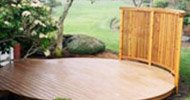
Free standing decks for above and inground pools
But today it is possible to combine concrete, stone, pavers, composite, or wood decking to achieve stunning and durable decks for inground or above ground pools and spas. In fact, contrasting materials with different visual and tactile qualities can sometimes soften the bland or monolithic weight of an expansive concrete slab.
This article will examine how two free-standing decks were used to enhance an above ground and an inground pool. It will explain the decking materials that can be used and the foundation selection which proved to be optimal for these specific applications.
The building techniques used in these projects do not in any way render traditional and proven building methods redundant or obsolete. Rather they show how builders can employ different solutions for different stylistic effects, building site conditions and budgetary considerations.

Foundation Considerations
Traditional frost footings are well understood. When one considers a deck attached to a house or other superstructure including second storey walkout decks, a deep frost footing is the recommended solution. Concrete footings come with known time, labor and cost considerations.
Engineered helical piers are also well understood and can support large buildings. In the right soil conditions, they can be installed quickly, and building can start the same day. But they require special machinery to install, and the cost is similar to concrete footings.

These two projects used a hybrid helical auger with a surface load plate call the Deck Foot Anchor™. It is a non-frost footing designed for floating or free-standing decks usually 6’ or less above grade. It has known compression and tension (pull out) data in a range of soil types and installs quickly in tight spaces using only a handheld ½” impact wrench. In fact, today’s 20V cordless impact wrenches by the major manufactures can drive up to a dozen 36” augers into clay soil in a single charge.
Section R403.1.4.1 of the IRC permits certain floating (non-ledger attached) decks, shed structures and the like to be supported by non-frost footings. The National Building Code of Canada has a similar section in Part 9 regarding foundations for free-standing structures. Since many decks are mid to low elevation and therefore can be free-standing, the Deck Foot Anchor™ opens up many possibilities. These two pool deck projects are great examples.
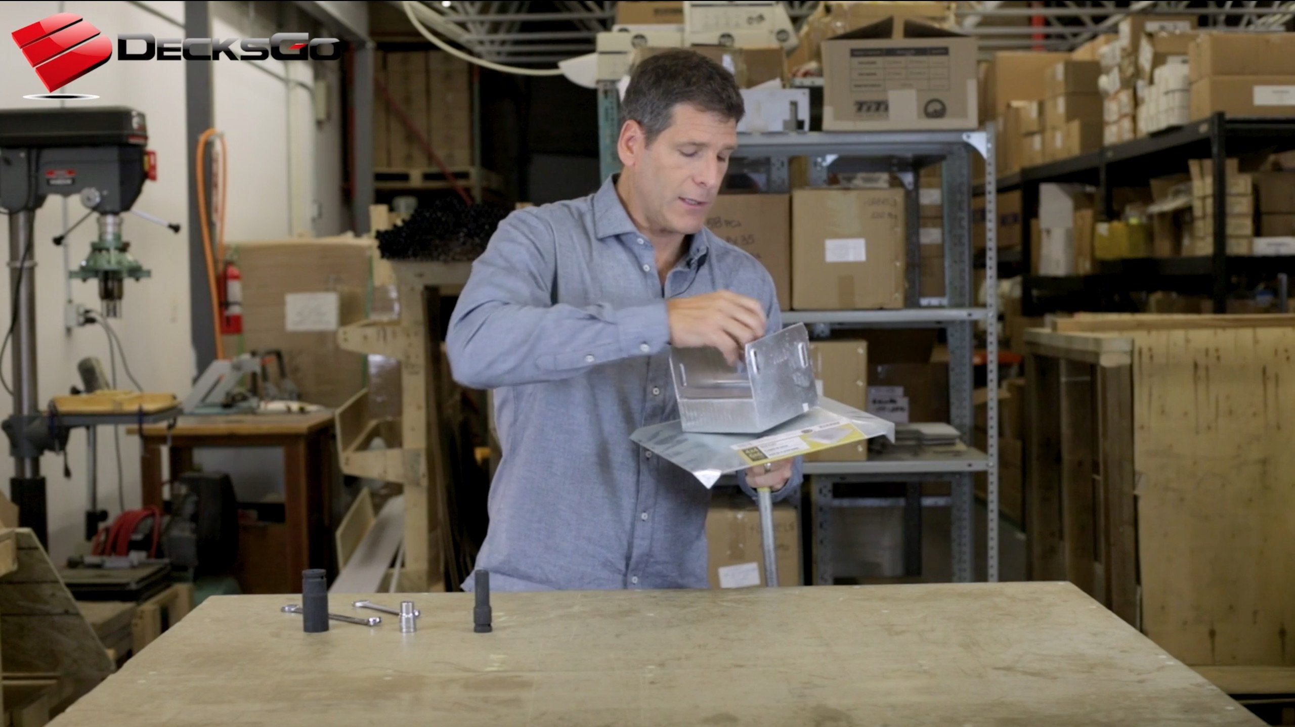
a hybrid helical pile - auger


the DECK FOOT ANCHOR™
However, before using any helical system including the Deck Foot Anchor™, it is important to know if the soil is conducive to a helical system. Rocks and roots can stop a helical blade. But the Deck Foot Anchor™ can be easily retracted and moved along a beam line to try again. And the post saddle has a lateral slide feature that provides up to 2” of adjustment. Also, the soil should be undisturbed and have a minimum bearing capacity of 1500 psf.
Decking Material For Applications Near Water

Treated Lumber
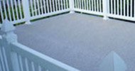
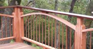
The above ground pool deck used treated pine with an oil-based stain and the inground pool deck used thermal treated wood left to age to a sliver patina. Wood decking that has a thin layer of water on it and a smooth sealed surface can increase the risk of slipping. In the case of above ground pool decks, the decking is subject to air flow from top to bottom and tends to dry quickly.
Composite Decking
Composite decking usually has aggressive embossed grain textures that provide further traction. Some composite decking is specifically designed for marine applications and are ideal for poolside applications.
However, water can wick through the end cuts of capped composite decking boards which can lead to swelling and potentially void manufacturer’s warranties. Therefore, end cut sealers are recommended.
Thermal Wood
Thermal wood is carefully heat treated to remove all sugars that otherwise provide food for bacteria and rot to find a home. It makes use of wood species such as Aspen, Alder and Ash which are hardwoods but not resistant to rot in an untreated condition. The grain lines are long and clean, and boards can be left in a natural condition to age to a slivery gray patina.

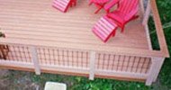
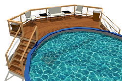
An Above Ground Pool Deck footings example

Decks like this are seen all around the country. They are generally simple to conceive and build and they improve access and enjoyment for affordable above ground pool decks. Depending on the extent that a deck surrounds a pool there can be as few as six or as many as a couple dozen footings required. Footings make a substantial portion of the total cost of any deck yet most homeowners that opt for an above ground pool do so based on cost considerations.
So, it makes great sense if a builder can construct a solution that economizes on cost when reasonably possible. A footing that is optimally designed for a free-standing structure, is quickly and easily installed by a handheld impact wrench and less expensive than full concrete or engineered helical
piers, is attractive to builders and homeowners. This deck was 16’x10’ and supported by six footings. The soil on the site was undisturbed and largely free of rocks and roots. It was also almost perfectly level. The pool was installed first and then the area of the deck was marked off. The sod was removed exposing the mineral soil.
The builder of this project went an extra step which is not required unless the soil is of very poor quality. But this builder used a gas-powered tamper tool and passed it over the footing locations as an extra precaution. It also made the entire area level. This is like how some large building sites are pre-loaded with mounds of soil for a couple of years before construction occurs.

site preparation

A small channel or trench was dug around the perimeter of the compacted area for paver stones to be eventually laid on edge to border the area under the deck.
Landscaping fabric was laid down and extended beyond the perimeter channel and the footing locations were accurately marked. The fabric was cut and folded open around each footing location so that the auger would not become tangled in fabric. The paver stones were set into the channel and formed a sharp border.
A load of ½” minus unwashed aggregate stone was spread out about three inches deep. It was given a light spray of water and the builder tamped the entire area down one more time. This gave the entire area a nice clean compact appearance.
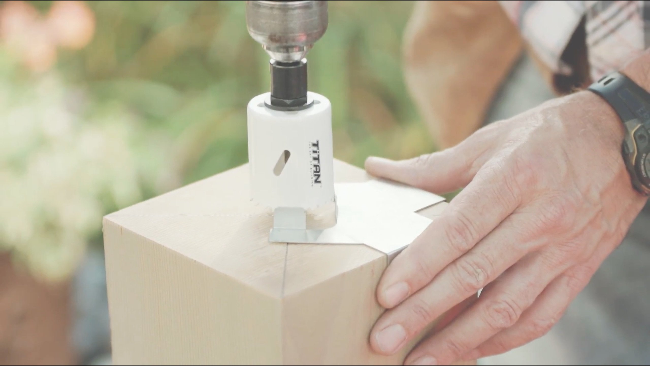
The augers were driven into the ground using a ½” drive impact wrench that could generate at least 350-ft-lbs of torque. The load plates and post saddles were installed according to the manufacturer’s instructions. The six footings were installed in about forty-five minutes.

Location And Distance Between Footings

The Deck Foot Anchors are generally set at about six feet apart so that the average tributary area above each footing is 36 sqft. Floor decks are to be designed to support 50 psf (10 psf dead load, 40 psf live load) and so this Rule of Thumb is good to follow. A 36 sqft tributary area with a full 50psf load over a single footing would impose 1800 psf on the soil below the load plate.
The Rule of Thumb is intended to be conservative and accounts only for the size of the surface load plate (1 sqft) and the known bearing capacity of the soil. But this keeps things simple for builders in making quick calculations. However, testing data from Intertek in October of 2021 from a site in Colorado confirmed that the helical blades alone
support a minimum of 1,100 lbs in clay and over 6,200 lbs in compressed sand. Given the hybrid nature of the Deck Foot Anchor™ these load values would be in addition to the carrying capacity of the surface load plate on the grade.
On this 16’x10’ deck three 10’ beams were set seven feet apart from each other and 12” from the opposing perimeters of the deck. The support posts under each beam were set at 6’-6” apart so that the beam cantilevered 18” beyond that last post to the edge of the deck. This created two different rectangular tributary areas of 32.5 sqft (6.5’x5’) and 23.25 sqft (4.75’x5’). These were very safe calculations, and this deck was designed to stand for decades if necessary.

Soil Bearing Capacity
As with any footing system, the important thing to remember is that the load imposed to the soil via the footing system should not exceed the soil bearing capacity. If this is respected the structure should theoretically remain stable indefinitely.
Therefore, if building on poor quality soil, it is conceivable that adding footings would reduce the load value imposed on the soil and within reason permit some decks to still be built with confidence.
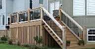
An Engineered Helical Pier And Frost

Both decks were free standing. A true helical anchor consists of a helical blade and a shaft. The load of the structure is carried by the blade, the torque, and friction of the soil along the length of the shaft. If the blade is below the frost line, the freezing and expanding soil is free to move up alongside the shaft. Whereas the Deck Foot Anchor™ is a hybrid system combining the benefits of anchorage and compression load resistance from the blade and shaft but with additional load
distribution through the surface resting plate to the grade. The helical anchor usually requires heavier equipment to install, and costs more but comes with onsite engineering reports and can therefore be used as a frost footing and can support very large permanent superstructures. The Deck Foot Anchor™ comes with a lower cost, and a known range of use but is generally very quick and easy to install. These attributes set it apart from engineered helical piers for certain decks that can be free standing.

A Hybrid Footing And Frost

During a deep freeze wet soil such as clay expands as the water freezes. This expansion causes the grade of the soil to rise relative to a superstructure that is unaffected by frost. The amount of the rise is dependent on the depth of the freeze and the amount of moisture in the soil. The load plate of the Deck Foot Anchor™ rests on the grade and is subject to the upward force of the expanding soil. This upward force is countered by the opposing tension force from the helical blade. If the blade is below the frozen soil and can resist the expansion pressure under the load plate, the Deck Foot Anchor™ would
theoretically remain stationary relative to the surface of the grade around it which would expand.
However, this is very difficult to predict and so the Deck Foot Anchor™ is most reliably used for floating structures where non-frost footings are permitted. A deck supported this way would move with the seasonal grade of the soil. These movements would be imperceptible unless accurate measurements could be taken against a stationary reference point. Decks like these two projects were excellent candidates for this type of footing because there were free standing.

Uplift Resistance

The above ground pool deck was about 4’ tall and the inground pool deck was set at ground level. The 36” footing was rated up to 1244 lbs of tension resistance in clay (4001 lbs in sandy soil).
The builder was quite confident that in the event of high winds, the pool deck would remain in place. In the event of a tornado the deck maybe be ripped apart, but the footings would likely still be in the ground.
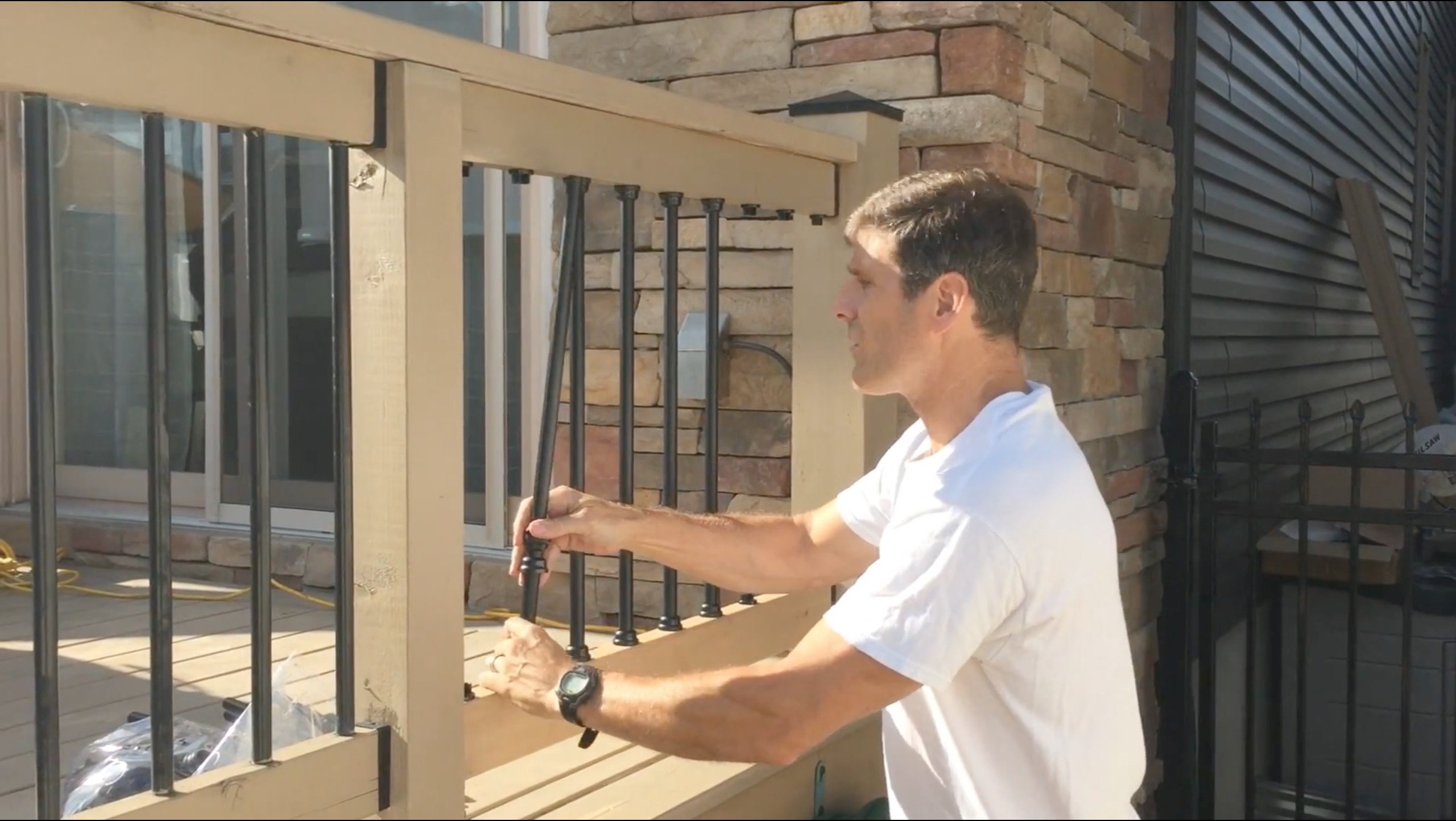
Construction Features Of The Above Ground Pool Deck

Large 6x6 posts were used and secured in the 6x6 post saddles with ¼” galvanized hex head screws. The screws were set near the bottom half of the elongated and embossed channels.
This is a unique feature of the Deck Foot Anchor™ called Terra-Shift ensuring that in the very rare event of any asymmetrical soil movement, by frost or any other cause, among a plurality of footings under the same beam, that the post under the most tension would be free to slide upward within the saddle thus preventing the post from every being pulled away from the beam.
The posts were braced with each beam to create a very stable sheer resistant platform. The beams were set into rabbet notches in the posts and secured with ½” carriage bolts. The 6x6 posts allow for this kind of construction and create a very strong load path to the footings.

Hurricane clips were used to secure the joists to the beams rather than the more common toe-nailing technique. As an added measure, preservative was applied to the ends of each blocking member within the joist bay.

Butting Up Against The Pool

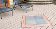
The deck was framed roughly in a hexagonal shape and the 5/4 decking boards extended up to four inches beyond the framing.
A minimum gap of ¾” between the pool coping and the deck boards. This was done to ensure that if the pool or the deck ever moved independently of each other, no damage to the pool would occur.
How It Performed Over Time

This deck was built in Ottawa, Ontario in the summer of 2012 and could not have been built in a better location for a test case of how the Deck Foot Anchor™ performs. The temperature can swing up to 100 degrees from January to July (-5F to 95F) and the soil conditions are among the most challenging in North America.
Here is a little background for readers unaware of these unique conditions. The Ottawa and St. Lawrence River valleys were submerged under melt water at the end of the last Ice Age forming what was known as the Champlain Sea. The seabed was known for a type of clay that had a very stable bond in salt water. But when the sea water receded and the soil was exposed to air and rainwater, the
clay’s stable bond was lost as the salt content was leached away leaving what is now known as Quick Clay or Leda Clay. Quick Clay is famous for its water retention, potential instability, and risk of landslide.
However, after almost a decade, this above ground pool deck has remained stable as a rock. It is level and strong as the day it was built. During one extreme winter the homeowner reported the deck appeared to be slightly higher relative to the coping on the pool than during the summer. But it returned to its original position in the spring and has performed exactly as it was designed to.

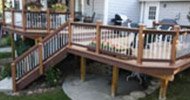
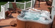
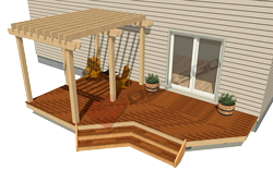
An inground pool deck footings example

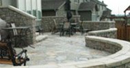
This deck was designed to marry concrete, and wood together. The homeowner had a very large area that he wanted to be covered and was trying to avoid a massive monolithic concrete slab.
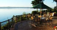
He felt that a combination of a concrete boarder around the deck butting up against a durable thermal treated deck all in the same horizontal plane would look the best and be comfortable to walk on in bare feet. The finished project does indeed achieve this look and blends beautifully with the transition from the deck to lawn.

How it Was Built
A paver stone patio was built tightly around the pool forming about a minimum 36” walkway. Along the perimeter of the walkway the pavers rested on a concrete foundation wall which was filled and compacted with granular stone as the base for the pavers.
Excavation

The area for the floating wood deck was extensively excavated between 24” to 30” below the level of the pavers and beyond the perimeter of the deck by at least 12”. A large load of granular aggregate was laid down over the entire area and leveled. The soil was undisturbed and stable clay without any rocks or roots.
Two main beams were planned at six feet apart running parallel to the length of the pool. Footings under the beams were set between six and seven feet apart with the deck framing intended to cantilever beyond the beams at most 24”.
Because the quality of the soil was well understood the builders used 36” augers to drive through the crushed stone base and anchor deeply in the soil below. The 6x6 post brackets cradled small 6x6 posts upon which triple laminated 2x8 beams rested and were toe-nailed to the posts using long RSS truss style screws. The 6x6 posts were secured to the saddles using ¼" hex head lag screws.
Joist tape was used to seal the tops of the beams and they carried the tape down over the beam to post and saddle to keep these components as dry as possible.

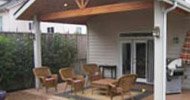
Butting The Deck Against The Concrete Foundation

A small ledge was formed into the concrete foundation and a 2x6 treated fascia board was fastened against the concrete with the top edge about a ¼" above the concrete ledge. The 2x6 was covered with 2” joist tape. With the beams all level the framing was built over top, and the joist ends were notched so as to rest on the 2x6 board against the foundation and about a ½" away from the pavers.
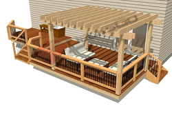
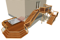
The joists were not secured to the 2x6 band but rested on top. The rest of the framing continued and along the backside of the deck in gentle jogs gradually narrowing near a staircase and hot tub spa which was set on a concrete slab. The access door to the tub was facing the end of the deck so removing section of framing was built to allow it to be removed easily when maintenance and access under the spa was required.


It is always wise to never fully encircle a hot tub spa with a deck. Doing so makes if very difficult to access for maintenance. A good strategy is to butt a deck up against two adjacent sides of a hot tub. This gives a built-in look but makes access easy from two other sides of the tub. The lumber used for the framing in this kind of application should be rated from ground contact because the design
feature of this kind of deck is the proximity of the different materials including the sod growing closely to the edge of the deck.
One way to further enhance the longevity of a ground treated lumber in this situation is to adhere 2” thick strips of closed cell foam around the band board so that the soil only contacts the foam. In the end the finished look is impressive.


the Deck foot can handle extreme weather
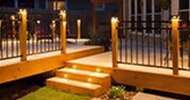
The decking for this project was a thermal treated ash made by Thermory. The boards a 5-½" wide by 1” thick and can easily span 14” joist bays. They also have tongue and groove ends so the boards can be fitted on against the other end to end and the joints can be over the joist bay. It is a very stable material and if left unsealed or treated is rated for twenty years and will age to a soft gray patina.

The entire deck structure is detached from the foundation of the pool and supported by the footings. If the deck were to move upward during it would be free to do so without any damage to the deck or pool.
The Deck Foot Anchor™ is well suited for this kind of application – even in a climate with very cold winters and here is why. This deck was built low into the ground below the surrounding grade where the cold air during winter cannot penetrate directly below the deck as it might otherwise for a deck elevated higher above the ground. In fact, during a long winter the entire deck surface is covered with a layer of snow which acts as an excellent insulator further reducing the impact of frost deep into the soil.
This was taken into consideration during the planning of this deck, and it has been tested over several cold winters without any observable annual movement. This deck was also built in Ottawa making it another excellent test case for the rest of North America where milder climate zones predominate.
Why Not Use Concrete Footings For This Deck
Concrete footings could have been used for this deck as they are sound and reliable. However, the homeowner chose the Deck Foot Anchor because it was significantly less expensive, quicker to install and construction could begin as soon as the footings were installed.
Pitfalls of deck foot system
Any kind of helical anchoring system is limited by the soil condition. Soil with extensive roots and rocks hinders the application of any kind of helical anchoring product.
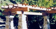
Since the Deck Foot Anchor employs a large load plate on the surface of the grade to increase compression load distribution it functions best for free standing structures like decks six feet or lower, shed platforms, boardwalks or pergolas which are stable and lightweight.
Testing Soil For Use With Helical Anchors

If in doubt, there are some simple inexpensive ways to test your soil to increase your confidence that the augers will work in your situation. A single auger can be purchased and tested in various locations on your site.
use a bit extender and a paddle bit
Or a 24” bit extender and a small 1” paddle bit with a drill can also give you a good indication if your soil is amenable to an auger system. Just drive the driver bit as deep as it will go into the soil and sacrifice the bit if necessary.
If all else fails, digging, forming, and pouring cement will get the job done.
Tips for building a deck around pool or hot tub, inground or above
Firstly, your site should be on undisturbed clean soil. If you are concerned that the soil is not fully settled, a tamper can be used effectively in footing locations.
Secondly, building on steep unstable slopes is not recommended.
Thirdly, the structure should be detached from any super structure where freezing soil conditions persist.
And finally, have a good understanding of the soil bearing capacity you are building on. Use enough footings to ensure the load imposed by each footing is sufficiently less than the soil’s bearing capacity.
If you keep these tips in mind you will well on your way to building a successful project.
Not every project will be suitable for a floating footing system like this. Each project and site location and characteristics should be carefully considered to determine what is the best solution for the intended function and use of the structure.
However, this is one more proven and tested alternative to concrete foundations that in the right circumstances give builders and designers more creative freedom and ease to build beautiful and durable decks around water features like above ground, inground pools and spas.


The Deck Foot Anchor™ is a DecksGo Recommended Product. It's one that we are confident you will be happy with. It's been tested in some of the harshest cold and sweltering heat temperatures and it has proven to be as tough as nails.
DecksGo was the first company to bring this product to the market, and you can expect more great "first" moments like this.
This is what we do - try to bring you leading edge building solutions before anyone else.
Home > Deck Foot Forum > Pool Deck Footings for Above Ground and Inground Pools
Fantastic Product!
Your product is fantastic I had about 5 of my neighbors just in awe of your deck feet when I was installing them yesterday. Hardest thing was to prep and level the ground before drilling these 6 deck feet in. Honestly installed six of the 6x6 Titan Deck Feet in about 20 minutes. My wife even said this is very cool.
Used my 1/2" impact wrench and it went down very straight and easy even in very thick clay soil. Honestly one of the best products I have seen. The new direct drive top on the post anchor is ingenious to say the least you can put it down and take it back up with no issues. 10 out of 10.
K. Bacchus - Toronto, ON
everything you ever wanted to know about the deck foot anchor...

I'm A Believer
I built a deck for my son earlier this summer in Columbus, Ohio using your Deck Foot product. I LOVE the Titan Deck Footers. And they were every bit as easy to install as your videos indicate, and the deck is perfectly level and solid. I'm a believer!
Rusty Allen, Columbus, OH
Would Take an F5 Tornado...
I wanted to let you know that we received the shipment of Titan Deck Footings and have begun construction on our deck. Thus far I am VERY pleased with your product. I think it would take an F5 tornado to rip up what I’ve built so far. :-) Seriously, I can’t thank you enough. Your deck footings have saved me countless hours and effort.
Eric Tucker - MA

Definitely Use Them Again
Easy installation into clay. 20 min for 3 deck foot anchors. Be sure to remove sod and add gravel to LEVEL ground. After that was complete it was simple to drill down the post part and then ratchet the nut tight.
I was using them on a small 10'x8' deck. I used a small post 21" to hold a beam for the joist.
It is solid and secure.
This product worked very well in this situation. NO cement to mix is a nice benefit. I would definitely use them again.
Chris Collins - Waterloo, ON
Very Slick Idea
Very slick idea and a lot less work than setting posts in concrete or using deck blocks.
For my project I would have needed 60 bags of concrete or a lot of deck blocks.
The Deck Foot is very light and the installation with an impact wrench goes very fast with minimal preparation. I used the 4x4 and would probably use the 6x6 next time to give some more room to notch posts.
Richard Todd - Kitchener, ON


Recent Articles
-
Pergola on brick paver
Apr 05, 25 05:36 PM
I have a brick paver patio that has been in for 10 years and I would like to know if the deck anchor will penetrate the gravel/sand base -
Durability of Titan deck foot
Apr 05, 25 05:20 PM
Hi, can you advise the estimated life of a Titan Deck Foot installed in the ground? How long is it expected to last? I live in an area in Ontario Canada -
10x8 6 person spa deck
Jul 26, 22 12:17 PM
I think I might be over-engineering this but I live in CT and I'm also worried about snow weight. Adding a 8x10 deck attached to existing deck, 2x10's

It's time to start
making your memories.

How-To
Go Learn More
© 2004-2026 Decksgo.com. All Rights Reserved.